Building Nia - Discovering the powers of RP2354
Hey there Wanderer
This post was supposed to go live a year ago, but here we are. I’ve finally wrapped up the first prototype (well, okay, not technically the first) for the Nia pendant, and I demoed it at Open Source Summit India in Mumbai this week.
Honestly, building a hardware badge from scratch and talking to people who genuinely connected with it was something special. We need more badge-hacking and maker energy at conferences like these, especially in India.
Rant aside, let’s get into the build 🤘.
The inspiration
A year ago, I came across a video by mitxela showcasing his fluid simulation pendant. It immediately caught my attention, and I knew I wanted to build something similar of my own.
I started with the physics first. Before diving into hardware or code, I needed to get a solid grasp on the mechanics, specifically, understanding what moves and what stays static within the simulation frame. This process wsa hugely accelerated with the help of Euler motion videos from the 10 Minutes Physics YouTube Channel (check them out).
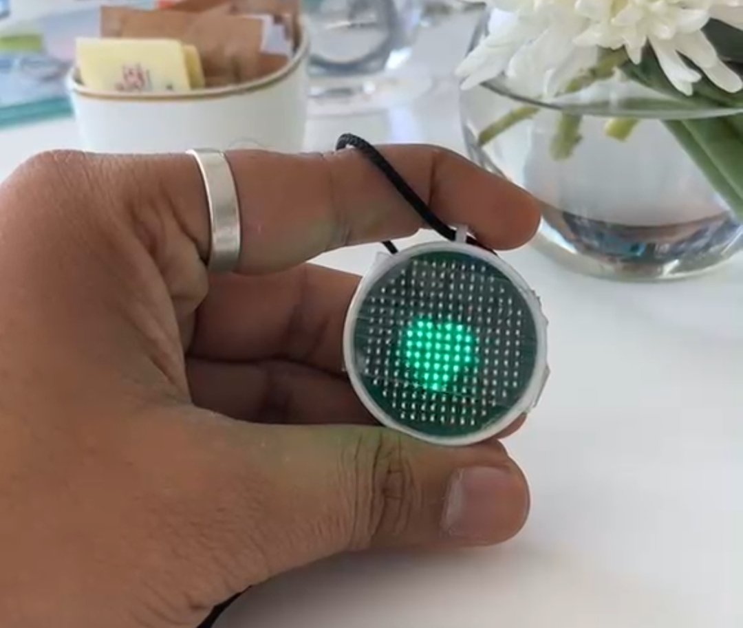
Next up was choosing the hardware. STM is great and I might switch to it in a version down the road just to see how far I can push it, but I’ve always had a soft corner for Raspberry Pi silicon. That affinity led me to the RP2354A for this project.
To support it, I built around the BMA400 accelerometer, a TPS3839A09DQNR supply voltage supervisor, a TPS7A0215PDQNR low-dropout (LDO) regulator, and an MCP73832-2-MC to handle the rechargeable cell.
Now that the hardware lineup is sorted, let’s look at the physics resources that guided my research. 10 Minute Physics was a huge help; his videos on Euler fluid simulation and FLIP simulations are self-explanatory and more than enough to get your bearings. Even so, I also took some time to dig into Robert Bridson’s classic work on fluid simulation.
I definitely recommend going through 10 Minutes Physics tutorials and JavaScript code while trying your hand at it. He’s done an incredible job with both.
Getting started with the PCB
BEFORE MOVING AHEAD DECIDE ON A KiCAD VERSION IF YOU HAVEN’T ALREADY!!
The first thing I did was dive into the schematic. I needed to figure out how to pull off the charlieplexing and build a prototype to make sure it actually worked. While Googling hepled with surface level knowledge, I found mitxela’s video more than sufficient for getting a better understanding. Once you understand how Charliplexing works, it feels like magic (it isn’t really).
Charliplexing cleverly uses the high, low and tristate states of the GPIO for operating the LEDs. Along with this having the LEDs arranged in a specifc order give you control over n(n-1) LEDs (where n = num(GPIO)). Having introed to charliplexing I started wiring a simple matrix. Which I later soldered into a prototype to test out the idea with pi pico.
I ordered a batch of LEDs to test things out. While the initial assembly wasn’t too tricky, making a proper schematic before permanently soldering anything to the board was an absolute lifesaver (and a non-negotiable step). I say this as routing the charliplexed matrix can be a little overwhelming if you are trying it for the first time (like me). Ki
For this prototype, I wired up a 8x8 matrix—which, naturally, started with designing the schematic to drive it.
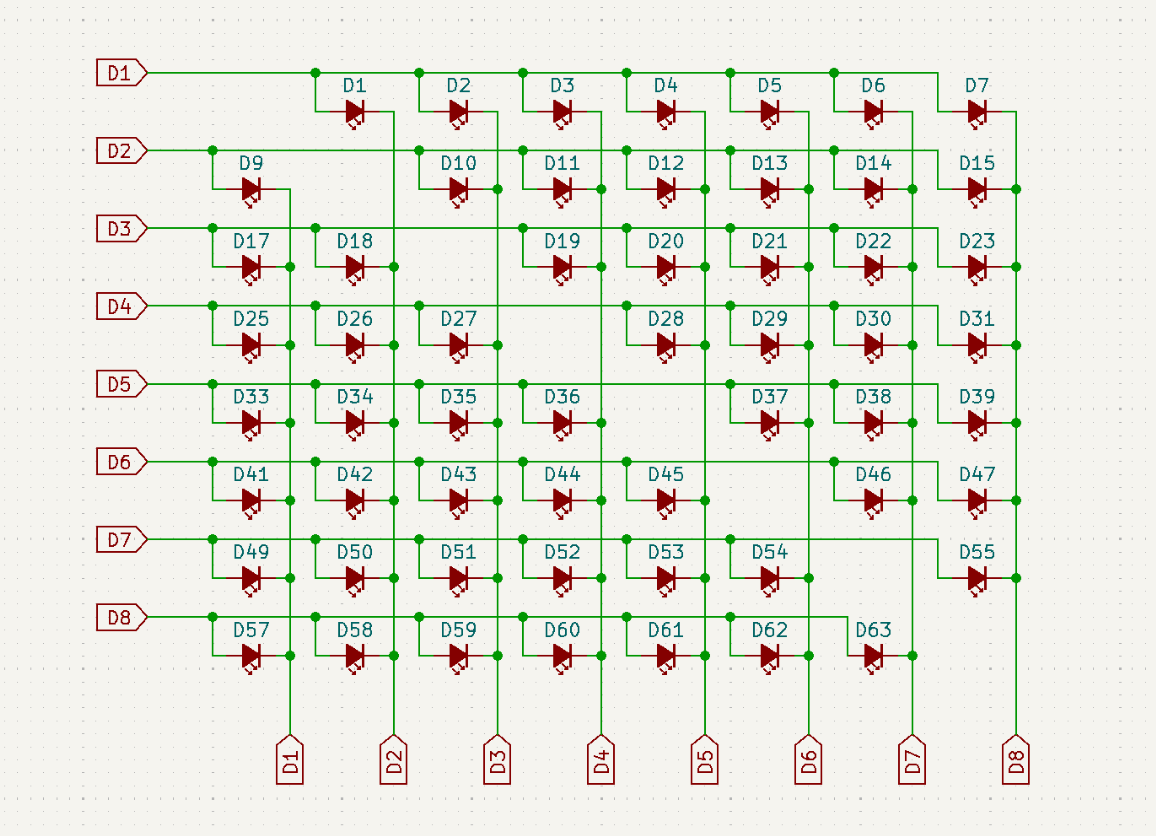
This is a relatively simple design that gives you a solid feel for charlieplexing without drowning in complex wiring. Being able to drive so many LEDs over just n GPIO pins genuinely feels like magic.
Of course, it comes with its own trade-offs. Managing a matrix this large increases your RAM overhead, which directly impacts your microcontroller choice. (More on MCU selection later in the article.)
I later upgraded to the desing from mitxela’s video. It helped me make soldering easier. I was able to visualize the routes better for soldering it on a PCB.
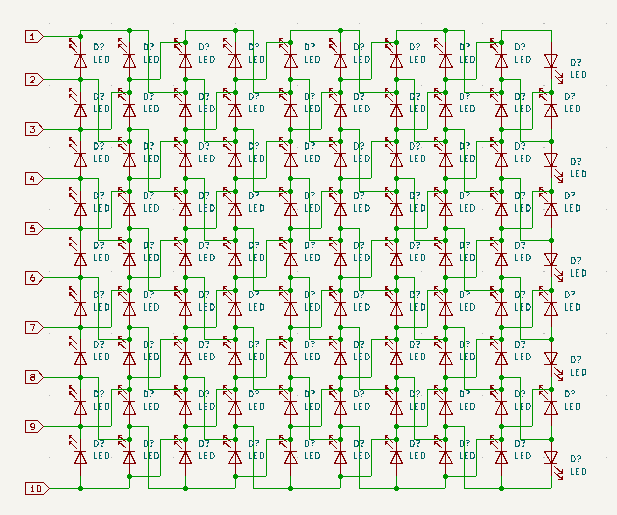
At first glance, the schematic looks totally convoluted and messy, but it’s actually pretty simple, you just have to know what patterns to look for.
As a good friend of mine once told me, “90% of engineering is identifying patterns. The rest is Googling” I have to agree with him. Once you zoom in and look closely at the repeating structures, you start to see how it all clicks together:
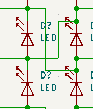
From there, you just need to replicate that single building block and wire the segments together to build out the full charlieplexed schematic. When I first started, I thought it would be way harder to wrap my head around. Honestly, it just took a bit of time and practice. I just had to dive in and start building it. And sure enough, once I got rolling, everything started clicking into place piece by piece.
If you’re tackling this yourself, I’d recommend starting with a smaller grid, like a 4x3 or 5x3 to get your bearings. Once you’re comfortable with the pattern, scaling it up by stacking those atomic pieces together is a breeze.
Prototyping
Next came handwiring the prototype, which was surprisingly fun. I initially ordered a spool of 0.1mm enamel-coated copper wire (the best decision ever), until I promptly lost it somewhere in my living room the next day, lol.
Scrambling for a backup, I grabbed some single-core aluminum wire I had lying around, stripped off the insulation, and got to work. Even with a simpler schematic, the wiring was a bit tricky-firstly because of the wire thickness, and secondly because of the dense matrix. I couldn’t do anything about the lost copper wire (trust me, I looked everywhere), but I could adapt. (I later found out I kept it in a soldering wire box, hallucinating it as spool of solder wire).
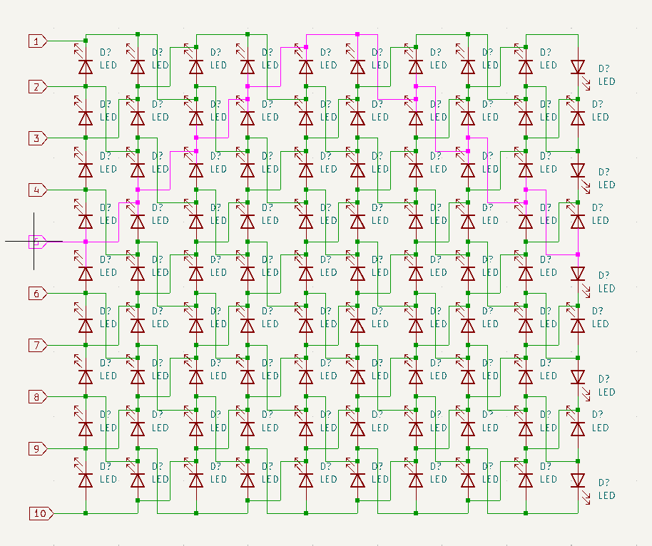
This is where KiCad came in super handy, especially the route/path highlighter tool: 
That tool was a lifesaver for viewing the schematic in a more layer-by-layer approach, letting me tackle one GPIO string at a time. The process was slow, but honestly, pretty relaxing. I started by cutting and stripping the wire into pre-cut strands, getting everything ready to go. Then came the best part: the actual soldering.

I totally miscalculated how many LEDs I’d need from the start. Once my first set of white LEDs ran out, I had to bring in some green ones I had lying around. Honestly, the mixed colors ended up looking pretty decent for proving out the concept atleast!
One big lesson learned here: use softer, thinner wire. These single-core wires were way too stiff, which later caused a ton of issues by putting unnecessary stress on the solder joints. If you’re building something similar, save yourself the headache and use softer wire. Ideally go with enamel-coated copper wire (FTW).
I wasn’t entirely sure how the finished prototype would turn out, but as the matrix came together, it started looking surprisingly cool. It’s definitely not my cleanest soldering job ever, but it gets the job done. Through the whole process, that KiCad route-highlighter tool was an absolute lifesaver.
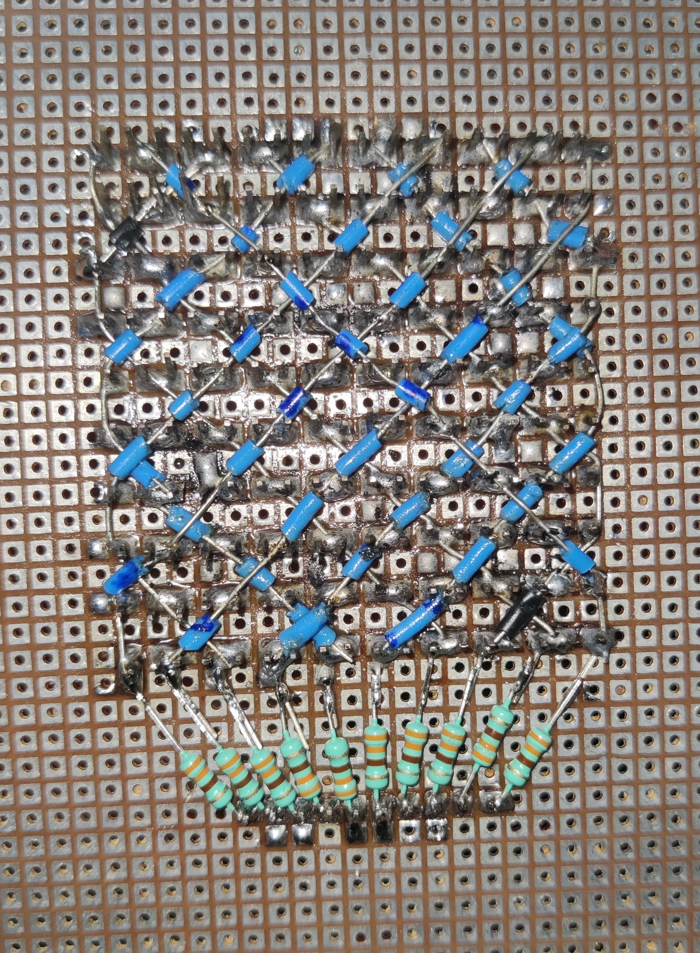
Here’s a look at the soldering work.
I started by running bare wires diagonally in one direction across the board. Once those were in place, I added segmented, stripped wires running in the opposite direction to complete the grid. To make sure the spacing was right, I first sized and pre-bent the segments directly on the PCB with just the LEDs soldered in.
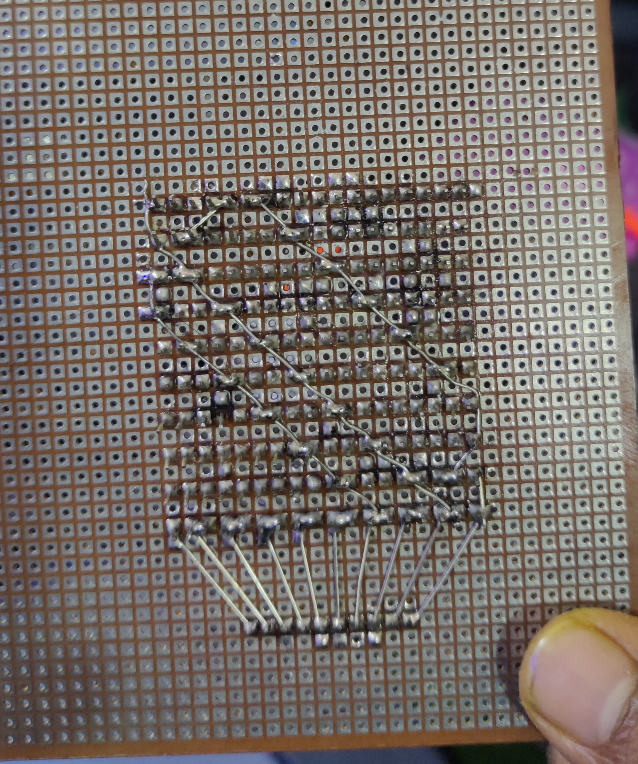
I kept the bottommost wire layer completely bare, which allowed me to use the insulated rubber coating on the upper wires to prevent shorts where they crossed. Again, going with thin, enamel-coated copper wire from the start would have been a much better choice!
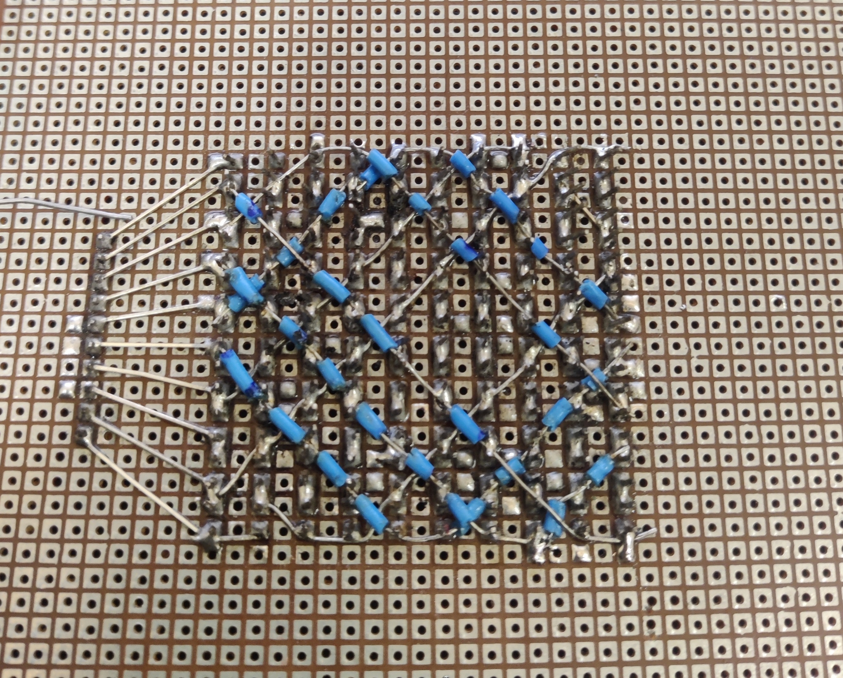
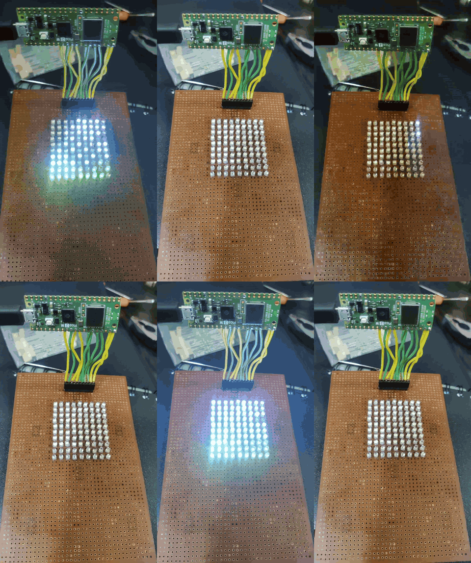
Here’s how the final soldering turned out.
Initially, I added 330 Ω current-limiting resistors to keep the LEDs safe. However, because I was multiplexing them at high switching speeds, the duty cycle per LED was so short that they couldn’t draw enough average current. Most of the LEDs ended up being way too dim to see, and a few didn’t even turn on at all. I ultimately pulled the resistors off completely to get the brightness back.
Here’s a demo video from one of the sanity tests I ran, mostly just to verify that all the LEDs actually worked and that I hadn’t fried anything during soldering: